The two surfaces have to be the same height to prevent the caliper from being mounted in a bind.
BUT before doing any machining it is necessary to see what needs to be done to center the abutment over the rotor.
Tolerances were not as tight in the 60's as they are today. There were +/- figures that parts were machined to because within those tolerances the parts would function as designed.
Before doing any machining bolt up your spindle, bracket and abutment. Determine what if any shimming or machining will need to be performed to get it mounted correctly.
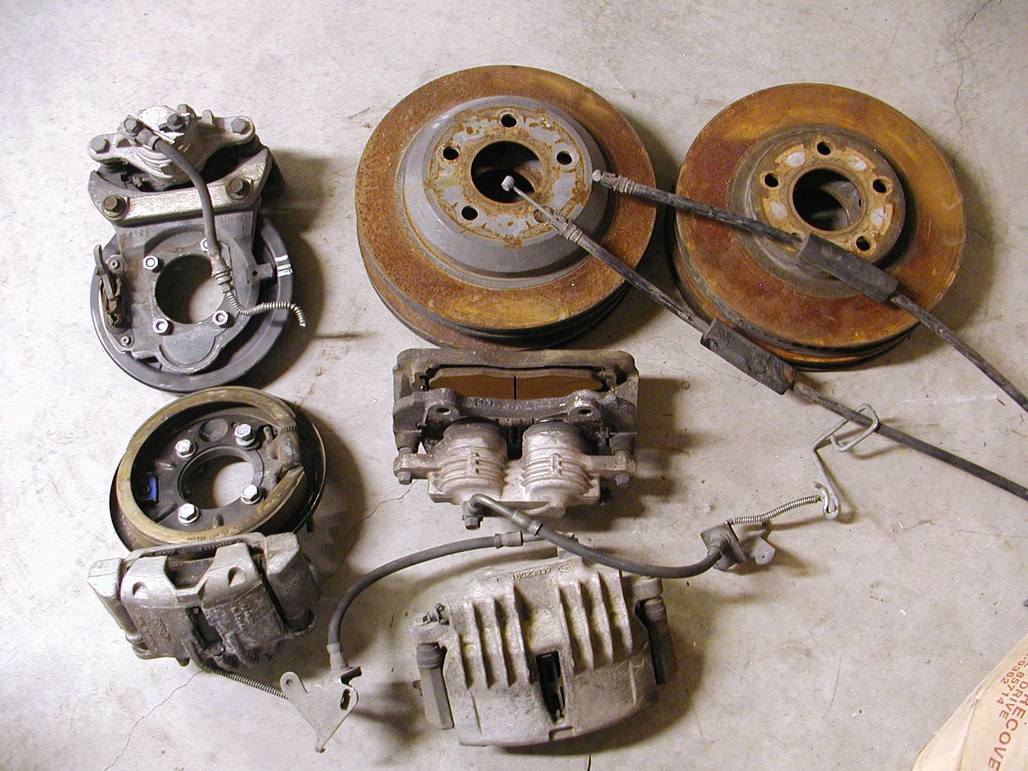
So step one decide which spindles you will be using for the conversion.
Step two have the drum hubs or disc rotors machined to fit inside the rotor.
Step three bolt the bracket on the spindle finger tight , do not bend the bracket with the bolts to fit the mounting bosses.
Step four install the hub on the spindle with the bearings properly adjusted.
Step five install the rotor on the hub and secure with a couple of lug nuts.
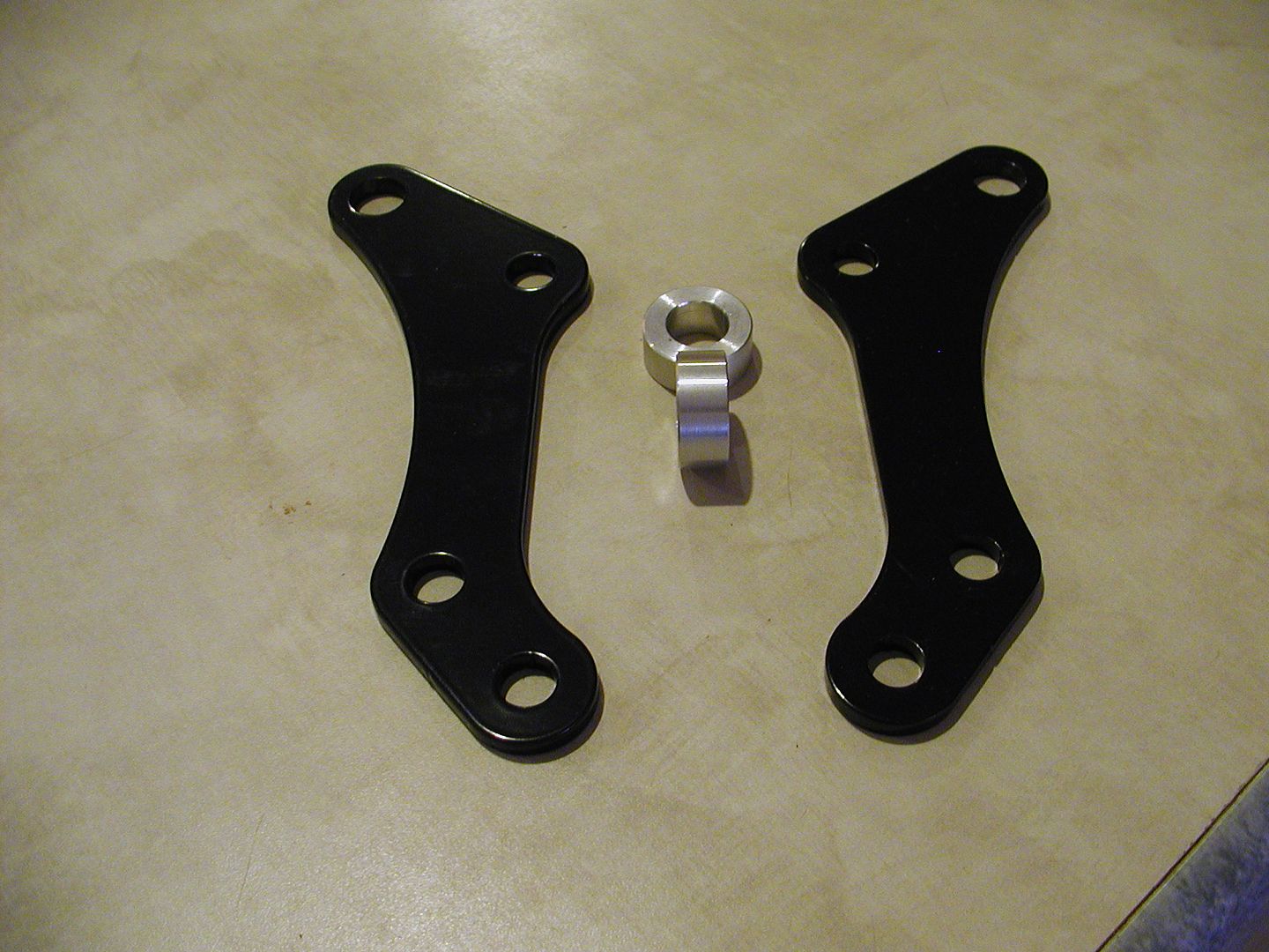
Step six bolt the abutment to the bracket.
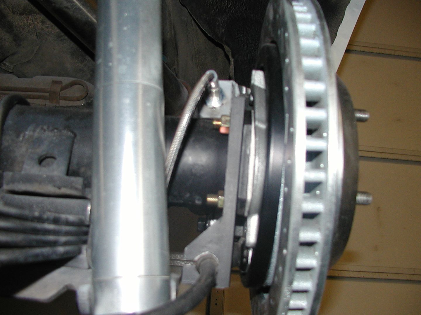
Now you can determine if the abutment needs to be moved either way to be centered over the rotor. If it needs to be moved towards the spindle machining will have to be performed, if it needs to be moved away from the spindle shims will need to be inserted and maybe the same amount of machining and shimming will not be required at both mount locations.
The abutment and placement over the rotor
Spindles may not be the same either, each one will need to be checked to see what is needed.
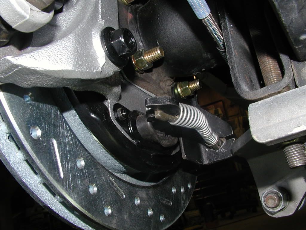
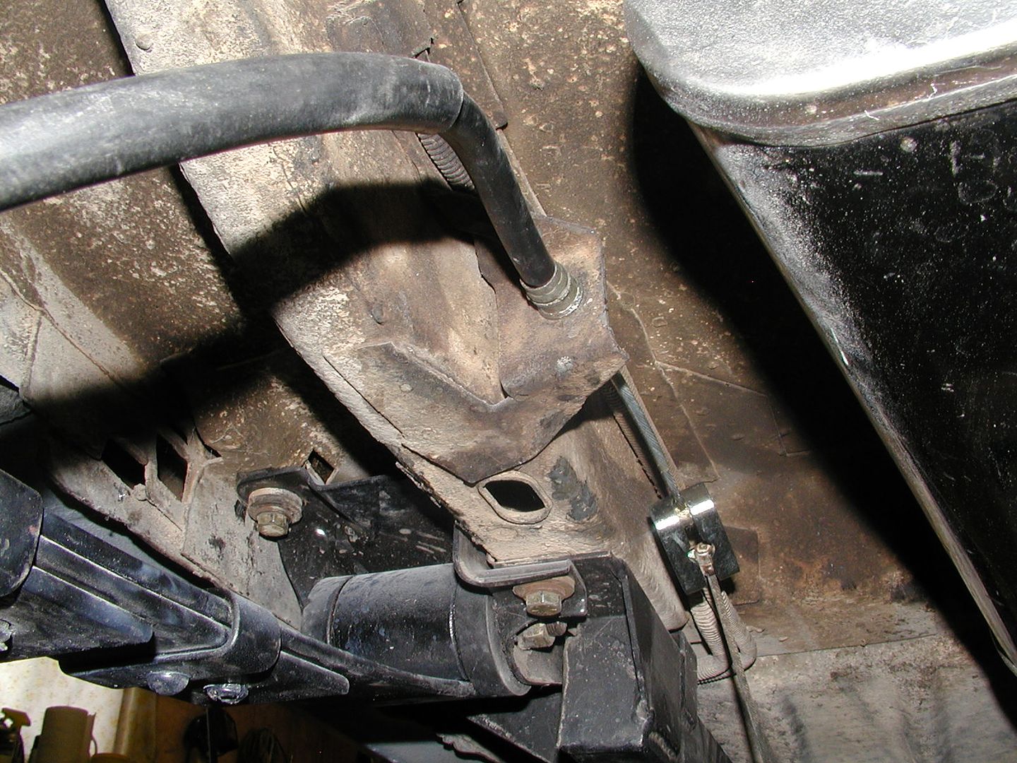
On the photos of my rear brake install the need for a shim was pointed out, the other side did not require one. The tolerances on the position the brake mounting flanges were welded to the housing were within spec but not the same.
Keep in mind your life and that of other people will be at stake if the brakes fail. There can be no compromise, install the parts to work as designed, use the proper fasteners and if any shimming needs to be done use material that will withstand the stress placed on it.


")